Safety Components on Guard
February 25, 2020
Protecting operators from the safety hazards introduced by automated machines and robotic equipment demands an understanding of both the appropriate safety guarding level and the machine safety components needed to get the job done. As always, the designer must identify the safety risks, plan the best ways of addressing them, and ensure the proper application of safety components.
Many safety standards and specifications come into play for protecting personnel around automated equipment. Machine safety requires comprehension of and adherence to all local, national and/or international safety codes to provide the proper safeguards. While that’s beyond the scope of this white paper, a brief introduction of safety standards for guarding is worth consideration.
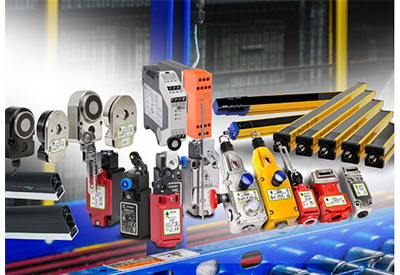
Once the appropriate safety guarding level requirements are defined through the use of a Risk Assessment process for an application, the necessary safety components must be selected to permit operators to perform their work while remaining protected by interlocked guard access and reliable safety control. These safety components include emergency stop buttons mounted for easy operator accessibility, as well as safety switches, limit switches, light curtains, mats and edges. All of these components are integrated together through safety relays or controllers to put the machine into a safe state, commonly by removing energy or stopping motion.
Key Specifications
Personnel with varying skill-sets work on, in or around automated production equipment. These personnel must be protected from machine hazards regardless of their experience or work responsibilities. Several national and international safety specifications are provided for this purpose (Table 1).
Specification 29 CFR 1910.212 identifies a variety of machines usually requiring point of operation guarding. ANSI B11.x specifications applies to all machines and equipment and includes many definitions and performance criteria on the use of interlocked guarding and light curtains. ANSI/NFPA 79-1991 and ANSI/RIA R15.06-1986 also discuss guarding requirements, as do ISO 13849-1, EN 62061 and ISO 12100 risk assessment.
Risk Assessment Risk Reduction
Before one can select the proper components for their safety system, a risk assessment, risk reduction process must be completed. This process would ideally be completed by a team consisting of a broad range of individuals including but not limited to designers, quality control staff, maintenance individuals, operators and even people that might be in the area of the machine at any given time.
The team should evaluate the system with all levels of safety training in mind. These are individuals that are very familiar with machinery and safety to those that has little or no safety training. The team will identify and evaluate hazards and risk factors. Then they will determine appropriate ways to eliminate the hazards and risks. This process must be iterative to eliminate hazards and reduce as far as practical. The Performance Level Required (PLr) for the safety functions will be the result of this iterative process. Once the PLr is obtained the proper components can be selected for the Safety related parts of the control system (SRP/CS). There are 5 performance levels, a,b,c,d and e.
Safety Guarding
A big part of selecting and designing safety components into a control system is determining the safety characteristics of the equipment to be guarded. What level of safety guarding is needed? It is important for the designer to understand the risk factors such as severity of injury, frequency of exposure and possibility of avoidance. These characteristics are defined in safety standards such as ISO 13849-1 and EN 62061.
Depending on the system architecture, applicable ratings may include: Performance Level (PL), such as PLe; Category, such as Cat 4; or Safety Integrity Level (SIL), such as SIL 3. The Performance Level Required obtained from the system Risk Assessment depends on the application.
Safety Integrity Level (SIL) is a measure of safety system performance in terms of probability of failure on demand, and there are four levels: SIL 1, SIL 2, SIL 3 and SIL 4. Performance Level (PL) is a similar measure to SIL, with levels of PL a, b, c, d or e. Higher SIL numbers or PL letters are associated with safer and more expensive protection regimes. Safer systems mean there is a lower probability the system will fail to perform properly. The reason costs for safer systems usually go up is due to increasing complexity, more demanding design efforts, higher component costs, and more intensive installation and maintenance labor.
The machinery safety standards help define the reliability, redundancy and fault detection which must be achieved by the safety system and each safety component. The designer, when specifying these safety components, must understand how to properly apply them in order to meet the needed category.
Safety Component Basics
Safety specifications make it clear that machine guarding (safeguarding) shall be provided to protect the operator and any other personnel in the machine area from hazards. These hazards include those created by point of operation, pinch points, rotating machinery, flying debris and sparks.
A variety of physical arrangements, such as fixed, adjustable, interlocked and perimeter barrier guards, are commonly used to protect machine operators and maintenance technicians. These barrier guards are designed and constructed to physically prevent plant personnel from having any part of their body in hazardous areas during machine cycles. Common barrier guard configurations include gates or guard doors to protect the operator from machine hazards. Before the machine can cycle, these gates and guard doors must be confirmed in the safe operating condition. Safety switches are used for this task, and there are many choices to satisfy regulatory requirements and provide a safe working environment.
Other safeguarding methods discussed in the safety standards include presence sensing devices such as light curtains and floor mats. Presence sensing technologies don’t physically stop a worker, but they are interlocked with the automation to prevent equipment operation that could harm personnel.
Regardless of the specific approach, the ultimate goal of all safeguarding is to protect personnel in the machine area by keeping any part of their bodies clear of danger zones while the machine is powered or cycling.
Safety Switch Overview
Safety switches are interlocking devices used in safety circuits to monitor and sometimes physically lock machine guards, doors, gates, windows or other machinery to protect personnel and machines. A variety of safety switch styles and mechanisms are available to reliably detect unsafe guard conditions (Table 2).
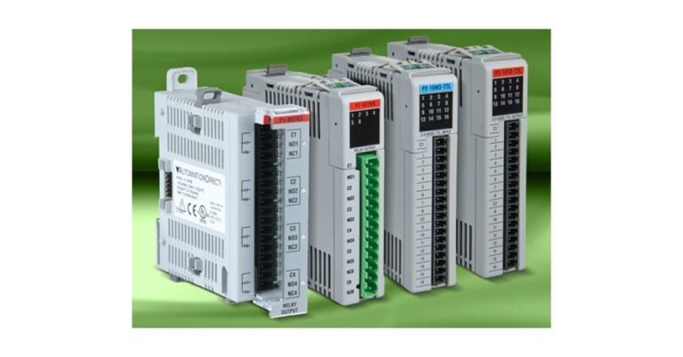
Single or dual electrical contacts from these switches are connected to safety relays or safety controllers, isolating power and de-energizing the hazard directly or through use of relays. This removes energy sources such as electrical power and/or pressurized air from motors, solenoids, pneumatic actuators and other motion-causing devices.
Regardless of the type of safety components used to help protect the operator from machine hazards, they must be wired to specialized safety relays or safety controllers to achieve fail-safe triggering of the defined safety function, such as presence sensing, access and guard door functions, emergency stop and safety muting. Muting is defined as, temporary automatic suspension of a safety function(s) by the SRP/CS (Safety-related part of a control system). Muting is a discussion for another white paper. The following paragraphs discuss the benefits, features, and typical uses for various safety switch styles.
Interlock Safety Switches
Machines with fixed guards needing a tool for removal don’t require safety switches. For this situation, a safety sign stating, “Do not operate machine without guards in place,” is acceptable. But if guards are movable then point-of-access protection in the form of a safety switch is needed to meet protection level requirements.
Tongue interlock safety switches are often used to monitor that a guard door or gate is closed. With these devices, a key (tongue) is mounted on a door, and it mechanically engages and actuates the fixed, door-frame mounted switch when closed. Personnel may open the guard at any time.
Locking tongue guard switches are like tongue interlock safety switches but add a spring and solenoid. These locking tongue guard switches can be configured to unlock/ release the tongue when energized or de-energized depending on the configuration specified. The automation system would be configured to unlock the guard at an appropriate time.
Hinge interlock switches can also be used to monitor guard doors and are available in different styles. Some mount to a pin on the top of the door, while others mount to the hinge pin and monitor the position of the door. They are compact and offer a degree of tamper resistance.
A cable pull switch is commonly used like an emergency stop switch, but instead of a single button, a cable is run the length of a machine, conveyor or production line providing quick access to any personnel near the cable. The cable is under tension so either a cable pull or cut can be detected, opening the switch and interlocking the local equipment to stop.
Non-Contact Switches
Non-contact safety switches are a special category providing similar functionality to mechanically operated safety switches. While mechanical switches are robust and long lasting, the non-contact variety can be even more so, and provide several other advantages. They feature near zero mechanical wear, leading to a longer service life. This lack of mechanical engagement also permits well-sealed switch housing designs offering improved environmental protection from water and dirt ingress.
The design of non-contact safety switches also makes them more tolerant to guard door misalignment. These switches will operate with varying degrees of misalignment, small swing radiuses don’t affect proper operation. Their small size allows them to be mounted in a variety of orientations and still operate.
Non-contact switches are typically available in non-coded or coded actuation with selection depending on the level of safety required. Basic non-contact magnetic safety switches are an example of the non-coded style and are a popular solution for guard door interlocking using simple magnets. These switches are passive; no separate power supply is needed to close the reed switch contacts, as the dry contacts are closed by the magnet.
Coded switches provide a higher level of safety. Magnetic- or RFID-coding in the switch ensures the proper actuator, using magnetic poles in a defined pattern or RFID code, is present before closing the switch contacts. These are active devices requiring separate power and proper device coding. A generic magnet cannot operate these coded safety switches. RFID-coded switches provide anti-tamper prevention through use of unique codes.
Non-contact magnetic locking RFID switches are also available to both monitor and lock machine guards and doors. A strong electromagnet provides locking forces of over 300 lbs. No mechanical engaging of a key is needed. The RFID coding greatly improves tamper-proof protection using uniquely coded actuators.
Safety Limit Switches
Safety limit switches provide mechanically operated switching contacts to monitor the position of machine elements and moving components for equipment and also safety related purposes, protecting both machine and operator. They are designed to be mounted for position sensing applications, such as guard doors, conveyor gates, machine beds and elevators. A range of housings are available with actuator heads and mechanisms such as levers, rollers and plungers operating either slow or snap action contacts.
Over travel or drift on overhead cranes and machine travel stops are conditions capable of causing catastrophic damage to the equipment. Safety limit switches can stop an overhead crane before it falls off the end of its tracks and can also protect other machinery from conditions not directly jeopardizing operator safety.
Safety limit switches can have the same form as common limit switches but are designed with safety standards in mind to assure possible machine failures are detected reliably at the required safety performance level. Positive opening normally closed (NC) safety contacts and a high mechanical life of over 5 million cycles are an important part of meeting the requirements of a safety system.
Safety Light Curtains, Mats and Edges
Fixed or hinged guards and gates are not always the best safeguard for an application. If constant or frequent safe access to the operating equipment is needed, then safety light curtains, mats or edges may provide a better option.
Safety light curtains, also called active optoelectronic protective devices, use photoelectric beams in a linear array to create a plane of detection between sender and receiver units. Any intrusion into this plane, such as an operator’s hand moving into the area, is detected. The resulting signal can be used to de-energize the equipment. This is a common way of providing protection where a process may require open and frequent access.
When carefully selected and applied, safety light curtains provide various levels or sizes of protection. Finger-safe, hand-safe or body-safe (access control) protection may be needed depending on the application. The distance the light curtain is mounted from the hazard also impacts the resulting type of protection. For reference only, light curtains with a resolution of ½ to ¾ inch can achieve finger-safe protection, approximately 1-inch resolution provides hand-safe protection and a 6- to 8-inch beam gap affords body-safe protection. Refer to installation instructions for protected object size, distance and speed requirements.
There are times where a light curtains are not practical for application. Safety mats and edges are two ways of achieving earlier detection that personnel are approaching a hazardous area, or that personnel are actually in the hazardous area. Safety mats detect the presence of personnel on horizontal surfaces, typically the floor, while edges can be used on any surface.
Safety contact mats consist of laminated layers forming pads available in various shapes and sizes, often laid on the floor to safeguard dangerous areas in and around industrial automated machinery. A person stepping on the mat triggers an immediate stop signal to the safety control system to stop hazardous motion of the machine or equipment. A variety of safety mat configurations, interconnect methods and tapered or straight edge styles provide protected area configuration flexibility.
Safety contact edges are pressure-sensitive sensors, like a bumper, applied to ensure the safety of closing edges at possible hazards such as crushing or shearing points. The safety function is triggered when a person or object contacts the edge, or an edge of moving equipment bumps into a person or object. These safety edge sensors are commonly installed on or around overhead doors and automatic gates.
Robot Safety Solutions
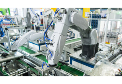
Robot material handling applications often require a range of safety components including more than one of the components described above. Beginning at some distance from the moving elements, large scale industrial robots often include a perimeter guard in the form of a cell (fence or cage) with multiple doors.
Each door would include a safety switch, either mechanically operated or non-contact. Instead of allowing personnel to open doors at will, it may also benefit the automated process to actively lock the safety doors through use of a solenoid locking tongue interlock switch or magnetic locking switch. With locks, an access request would be required to cycle stop the machine in a controlled manner before entry.
Due to restrictions of the cell fence, the robot’s base-axis rotation may need to be limited. A safety limit switches are often used to detect a cam physically mounted to the robot base. Software limits programmed in the robot software would limit the rotation to 90 to 270 degrees, for example. However, physical safety limit switches would be used to detect if the robot rotated outside of the programmed range of motion, trigging an emergency stop.
These robotic cells often collaborate with humans. For example, an operator may place a component into a fixture for robot pickup. To safeguard the operator in this application, the operator would reach through a light curtain to place a part. The robot would slow or safely stop depending on its position when the light curtain safety is triggered.
Conclusion
It is crucial to properly implement safety provisions in order to protect operators of machines and robots. Numerous standards are in place to help guide safety design efforts. Many safety components are available and automated equipment often requires a variety of them. Take the time to understand the many safety standards and select components to properly safeguard both personal and machines.
For more information, visit www.automationdirect.com.


