Connectivity Corner: The As and Bs of IO-Link

MC-11-AsBsOfIOLink-400.jpg

October 7, 2021

By Colin Cartwright, System Sales Manager, MURR CANADA

Now we’re all back from our summer breaks, it’s time to get back to work and continue our Connectivity Corner series. Last time out, we looked at the similarities IO-Link has with USB in “Why IO-Link is Like an Industrial Version of USB”.

Over the next couple of months, we’re going to dig deeper into some of the technical aspects of IO-Link so you can have a better understanding of the data types, communication speeds, maximum transmission distance, and the different power classes of IO-Link.

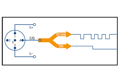
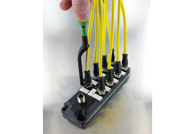
Let’s start with the connection pin-outs you’ll typically find on an IO-Link device. With most IO-Link devices coming with M12 connectors, we’ll use the pin-out configuration of an M12 connector for our examples. The most basic version of IO-Link only requires three connections to be made: Pin 1 = 24VDC, Pin 3 = 0V, and Pin 4 = IO-Link Communication. Yes, pins 1,3, and 4 are the same pins you would usually use to connect regular sensors. Uniformity is one of the nice things about the IO-Link standard. An IO-Link device requiring only these three connections is categorized as a Class A device.
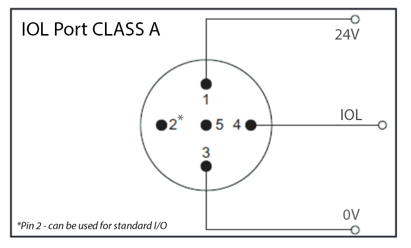
IOL-Port_Class_A.jpg

Some IO-Link devices (usually output devices like valve manifolds) need additional power so for these devices you will also need to connect Pin 2 to 24VDC and Pin 5 to 0V. You can either use the same power supply or a different power supply for these connections. If your IO-Link device requires all five pins to be connected, then it is categorized as a Class B device.
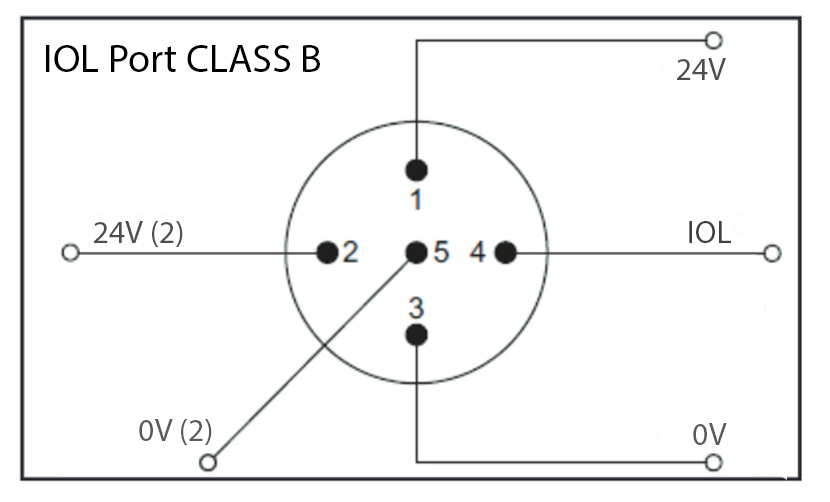
IOL-Port_Class_B.jpg

So other than an extra two wires to connect, what’s the real difference between Class A and Class B?

Well, it basically comes down to the amount of current available on pin 1. The IO-Link standard (IEC 61131-9) specifies that the maximum current for Class A devices should be 200mA. That’s plenty of power for input devices like proximity sensors or cylinder reed switches, but it’s a little low to drive a hydraulic solenoid or a valve bank with 16 valves. The Class B standard was therefore introduced to provide extra power for these types of IO-Link devices. There is no current limit specified for Class B devices in the IO-Link standard, but as the individual pins of M12 connectors are limited to 2A, the maximum amount of current that can be supplied to a Class B IO-Link device is typically 2A.

One major benefit of IO-Link Class B connectivity is the potential to connect output devices to safety systems. Using a special T-Coupler will enable you to connect the actuator power separately to the IO-Link power. For example, pins 2 and 5 can be connected to a safety relay or safety controller which will enable you to shut down the actuator power without affecting the communication to the device.

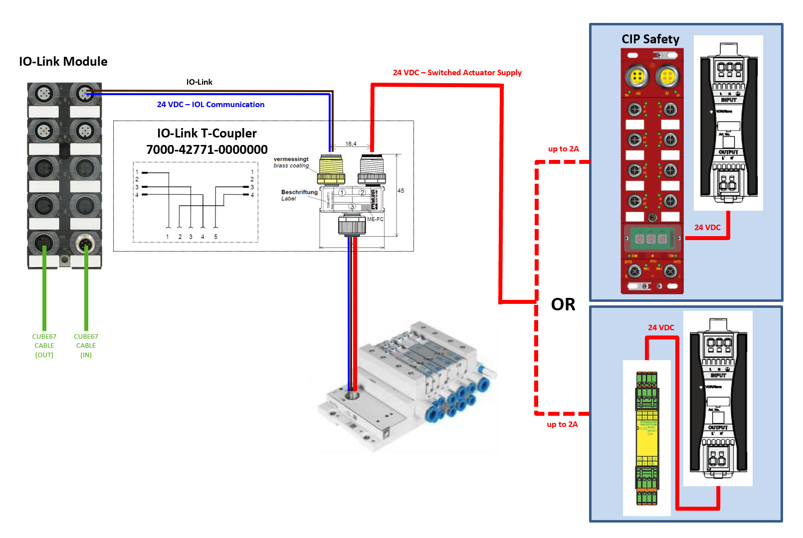
Here is an example showing a Murrelektronik Cube67 IO-Link Module controlling a Festo valve bank with an IO-Link interface using one of our IO-Link T-Couplers to separate the actuator power.
IOL-Class-B-Safety.jpg

In this example, an M12 IO-Link port on the IO-Link module provides basic power and IO-Link communication to the valve bank via pins 1,3 and 4 on the left side of the T-Coupler, while the power for the valve solenoids is supplied separately from a safety relay or safety I/O module connected to pins 2 and 5 on the right side of the T-coupler. When the safety outputs feeding the switched actuator supply are turned off there will be no power to pin 2 on the valve bank connector to energize the valve solenoids so they cannot move, however, IO-Link communication is still enabled.

With many pneumatic manufacturers now offering IO-Link interfaces for their valve banks, I think this is now the most economical and effective way to connect valve banks. It reduces your electrical connection to a single 5-pole M12 cable and enables you to locate a valve bank anywhere there is an I/O module with IO-Link Class B ports, rather than running a cable back to your panel or adding an additional IP address.

That’s it for this month. Next month we’ll be digging deeper into the technical side of IO-Link data types and communication speeds. Have a great month!

Related Articles


Changing Scene


Sponsored Content
The Easy Way to the Industrial IoT

The way to the Industrial IoT does not have to be complicated. Whether access to valuable data is required or new, data-driven services are to be generated, Weidmuller enables its customers to go from data to value the easy way. Weidmuller’s comprehensive and cutting-edge IIoT portfolio applies to greenfield and brownfield applications. Weidmuller offers components and solutions from data acquisition, data pre-processing, data communication and data analysis.

Visit Weidmuller’s Industrial IoT Portfolio.


ADVANCED Motion Controls Takes Servo Drives to New Heights (and Depths) with FlexPro Extended Environment Product Line

Advanced Motion Controls is proud to announce the addition of six new CANopen servo drives with Extended Environment capabilities to their FlexPro line. These new drives join AMC’s existing EtherCAT Extended Environment FlexPro drives, making the FlexPro line the go-to solution for motion control applications in harsh environments.

Many motion control applications take place in conditions that are less than ideal, such as extreme temperatures, high and low pressures, shocks and vibrations, and contamination. Electronics, including servo drives, can malfunction or sustain permanent damage in these conditions.

Read More


Service Wire Co. Announces New Titles for Key Executives

Bruce Kesler and Mark Gatewood have been given new titles and responsibilities for Service Wire Co.

Bruce Kesler has assumed the role of Senior Director – Business Development. Bruce will be responsible for Service Wire’s largest strategic accounts and our growing Strategic Accounts Team.

Mark Gatewood has been promoted to the role of Vice President – Sales & Marketing. In this role, Gatewood will lead the efforts of Service Wire Company’s entire sales and marketing organization in all market verticals.

Read More


Tri-Mach Announces the Purchase of an Additional 45,000 sq ft. Facility

Tri-Mach Elmira Facility

Recently, Tri-Mach Inc. was thrilled to announce the addition of a new 45,000 sq ft. facility. Located at 285 Union St., Elmira, ON, this facility expands Tri-Mach’s capabilities, allowing them to better serve the growing needs of their customers.

Positioning for growth, this additional facility will allow Tri-Mach to continue taking on large-scale projects, enhance product performance testing, and provide equipment storage for their customers. The building will also be the new home to their Skilled Trades Centre of Excellence.

Read More


JMP Parent Company, CONVERGIX Acquires AGR Automation, Expanding Global Reach

Convergix Automation Solutions has completed the acquisition of AGR Automation (“AGR”), a UK-based provider of custom, high-performance automation design and systems integration primarily to the life sciences industry.

Following Convergix’s acquisitions of JMP Solutions in August 2021 and Classic Design in February 2022, AGR marks the third investment in Crestview’s strategy to build Convergix into a diversified automation solutions provider targeting the global $500+ billion market, with a particular focus on the $70 billion global systems integration and connectivity segments. Financial terms of the transaction were not disclosed.

Read More


Latest Articles

  • Implementing Functional Safety Requirements

    Implementing Functional Safety Requirements

    The Safety Functional Requirements Specification (SFRS; sometimes referred to as SRS or Safety Requirements Specification) is the plan for the safety controls on a machine and is the second step of the safety lifecycle. The SFRS document serves as a framework for the safety control system design, is informed by prior work done in the… Read More…

  • From Endress+Hauser, 24/7 Digital, Plant-Wide Health Monitoring for Rockwell Systems Optimizes Workflows and Processes

    From Endress+Hauser, 24/7 Digital, Plant-Wide Health Monitoring for Rockwell Systems Optimizes Workflows and Processes

    Endress+Hauser’s Asset Health Monitoring Solution–Rockwell Edition, now available for installation, provides operators with a centralized, digital overview of plant-wide device health to avoid unscheduled shutdowns and accelerate troubleshooting. It not only presents early visibility of problematic devices but distinguishes itself by adding likely causes and remedies to such a report so problems can be fixed… Read More…