Murrelektronik Canada: How to Choose a Sensor Cable
April 1, 2021
By Colin Cartwright, System Sales Manager, Murrelektronik
When I started as a controls engineer more than 30 years ago, choosing a sensor cable was relatively easy because there weren’t very many options to choose from. It was 1990 and if a sensor had a connector (many were still widely available with screw terminals at that time), it was either a 7/8 Mini connector or a M12 connector. The smaller M8 style connector had only just been released so sensor manufacturers had not really adopted it yet.
Back then, choosing a sensor cable basically came down to four things: the connector type (7/8 or M12), the connector style (straight or right angle), the number of poles/pins (3 or 4) and the length of the cable. Double-ended cables were available, but as we were usually terminating everything back at the main panel, we rarely used them. Oh, I nearly forgot – you could choose any colour or jacket material as long as it was yellow PVC!
These days, you’ll struggle to find a sensor with a 7/8” connector, but M12 and M8 connectors have truly stood the test of time. They are definitely the most common connectors found on sensors today. Now connectors haven’t changed much, but there has been a huge advance in the types of material available to make sensor cable jackets, so we are no longer stuck with a yellow PVC jacket as our only choice. We’ll dig into this little more later.
Having selected sensor cables for thousands of automation projects over the years I wanted to share some of the things I always consider when choosing a sensor cable.
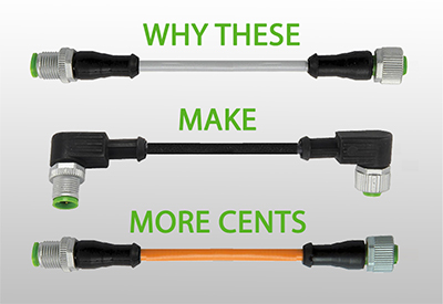
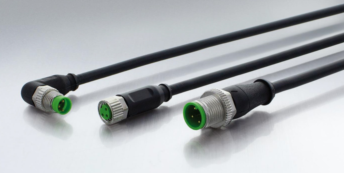
Let’s start off with the sensor connector itself. Most sensors have M12 or M8 male connectors with 3 or 4 poles/pins, so choosing the sensor end of the cable is quite simple. Once you’ve determined the connector type and pin configuration, the only other thing you need consider is the orientation of the cable relative to the sensor. You can choose straight or right-angle depending on whether you want your cable to run inline or perpendicular to the sensor.
You can skip this next step if you only require a single-ended sensor cable, but if you plan on connecting your sensor to an IP67 I/O module you will need a double-ended cable, so you will need to know the size and type of the ports on the I/O module. An I/O module with M12 female ports is simple because the pin configuration/layout is same for M12 male connectors no matter if they have 3 or 4 pins. However, pay more attention to IP67 I/O modules with M8 female ports because the pin configuration on 3-pole and 4-pole M8 male connectors are different. You cannot plug a M8 male 3-pin connector into a M8 female 4-pole port, or vice-versa. If you ever do run into a situation where your I/O module has M8 ports with 3 poles and you have sensor with a M8 4-pole connector, you’ll need to use a field-connector or a Y-cable to connect to two ports.
![]()
Next, you’ll need to determine if your sensor needs a shielded cable or not. Most sensors with a PNP or NPN output do not require a shielded cable, but if your sensor has an analog output like 4-20mA or 0-10v you will need to select a shielded sensor cable to prevent the analog signal being affected by noise.
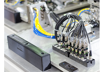
Once you selected your connectors and determined if shielding is required or not, you’ll need to work out the length of your sensor cable. This is not as straight forward as it seems. Depending on where your sensor is mounted, you will typically need route your cable up and around your machine so if you’re connecting your sensor directly to a PLC input card you’ll need a longer cable. If you have several sensors, then an IP67 I/O module will substantially reduce the number of cables you have to route back to your panel. Using an IP67 I/O module will also keep your sensor cables nice and short as well as reduce your installation time. When calculating the length of your cable don’t forget to include any vertical routing along with the horizontal routing of the cable!
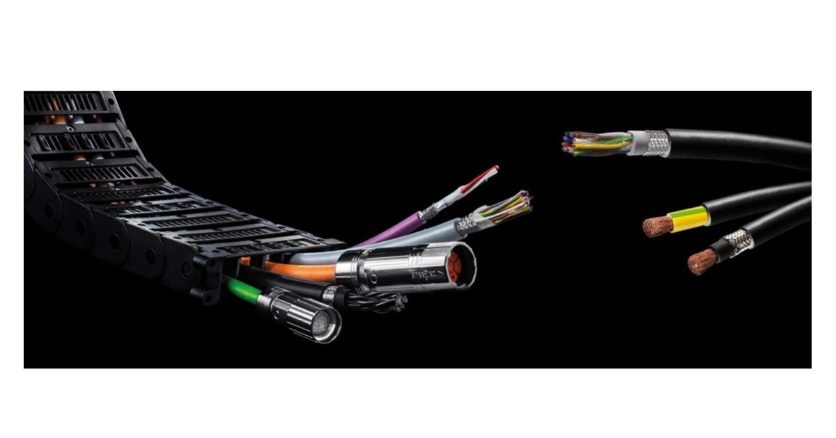
We are nearly there, but this next step is probably one of most important because it can make a huge difference to the reliability of your machines. We are talking about the operating environment and the possibility of cable movement during machine operation. If these factors are not considered, your sensor cables may end up causing a lot of breakdowns and unscheduled downtime. Let’s cover the operating environment first – There’s a huge difference between the operating environment of a welding cell in an automotive plant and a meat slicer in a food processing plant. A sensor cable designed with a jacket material resistant to weld spatter will not be very good at resisting the high-pressure water and chemical solutions used to wash down a meat slicer, or the other way around. There is not enough space here to dive into all the different types of jacket material available for different environments, but it’s definitely something you should look into when choosing your sensor cable.
Now, what about cable movement? There are sensor cables designed for no movement and there are sensor cables specifically designed for motion type applications with a lot of bending and/or twisting. For example, a basic sensor cable installed in a C-Track will likely fail at around 1-million bend cycles. A sensor cable that has been designed for constant bending applications like a C-Track has a more flexible jacket material and finer strands of wire. This increases the amount of bend cycles to 10 million at very little extra cost. That’s a lot less cable changes and much more up time! Some sensor cables are also designed for applications with a lot of twisting or torsional movement. A basic sensor cable is limited to 180 degrees or less of twisting, but a robotic sensor cable will give you a full 360 degrees of torsional movement so will last a lot longer in those type of applications.
The operating environment and consideration of cable motion are often overlooked, but if you care about the reliability of your machines, these are important factors to consider when choosing a sensor cable.
The last thing to consider is the colour of the cable. This is generally not a big deciding factor, but I do know some machine builders like to use different sensor cable colours to identify the type of sensor attached. i.e. black cables for photo or proximity sensors and grey cables for cylinder reed switches. It’s really up to you but some colours might have longer lead-times so double-check with your sensor cable supplier to make sure the colour you want is readily available.

I think that’s everything covered. The only other possible thing you might want to consider would be the wire gauge for really long sensor cable runs where voltage drop might be an issue.
In summary, sensor cables are an integral part of every control system but are often chosen on price rather than the type of application or environment they will be operating in. This often leads to unnecessary breakdowns and can put a big dent in the reliability of your machines. On the other hand, getting some input (pun intended) from a connectivity specialist, or taking a little time to choose the right sensor cable yourself, will improve your machine uptime and bolster your reputation for quality and reliability. Next time you choose a sensor cable, which outcome would you prefer?
Colin Cartwright is the System Sales Manager at Murrelektronik Canada and has nearly 30 years of controls and automation experience. He specializes in I/O systems and works closely with machine builders and system integrators to help them optimize their control systems and reduce wiring/commissioning times.

