How IO-Link Works – Communication & Data Types
March 8, 2022
By Colin Cartwright, System Sales Manager, Murrelektronik Canada
Last time out, we talked about the As and Bs of IO-link and explored the differences between IO-Link Class A and Class B connectivity. If you missed that one, you can read it here.
This time around, we will look at IO-link communication and data types. Let’s start with a quick overview of how IO-Link communication works.
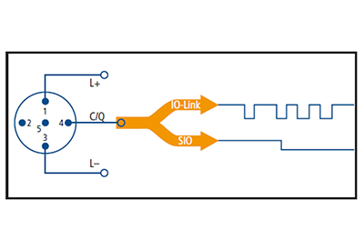
IO-Link devices communicate with the IO-Link master via bi-directional serial communication on a single wire connected via Pin 4 of the master port. The IO-Link communication is master/slave-based, with the IO-Link master initiating requests and the IO-Link device responding.
Due to the nature of using a single wire for serial communication, IO-link data can only be transmitted in one direction at a time to avoid data collisions. If an IO-Link device is not detected, the IO-Link master will revert to standard IO mode.
Communication is initiated by the IO-Link master when it sends a wake-up pulse of at least 500mA to the device. When the device receives the wake-up request, it sets itself to receive mode. Once the device is in receive mode, the IO-Link master sends multiple messages at different baud rates to determine the communication speed of the device. Once the IO-Link master receives a baud rate acknowledgement from the device, it automatically sets the baud rate to COM1, COM2 or COM3 to match the device.
Interestingly, the IO-Link Consortium chose to define the communication speed/baud rate of an IO-Link device as COM1, COM2 and COM3 (slowest to fastest), which some of you might remember, was used to identify serial ports, not the baud rate, in the old days.

During the design phase of an IO-Link device, the device manufacturer will decide on one of the three COM baud rates. The device is then manufactured with the COM/baud rate permanently set. In other words, the COM/baud rate of the device cannot be changed later.
These days most IO-Link device manufacturers use COM2 or COM3, so you’re unlikely to find many COM1 devices out there. If you do come across one, please send me a photo!
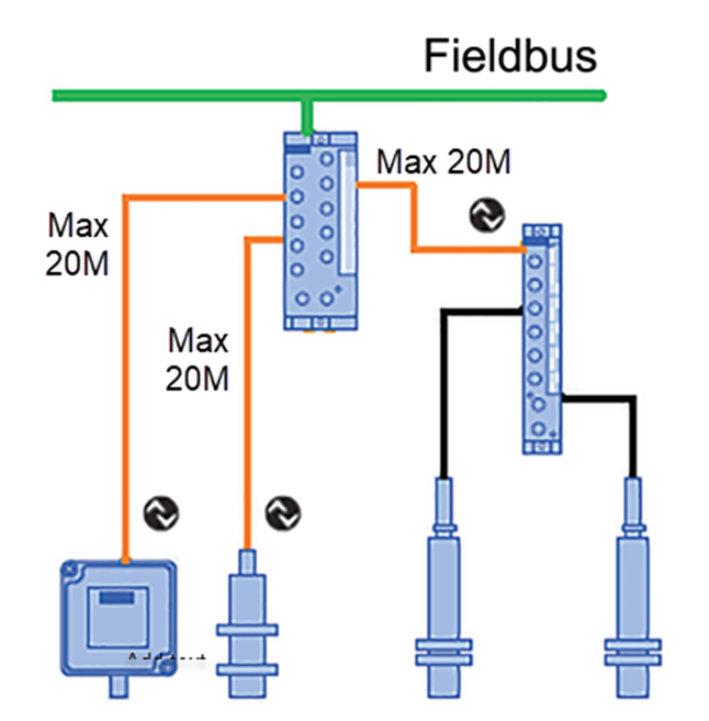
The maximum communication distance between an IO-Link master and an IO-Link device is 20 meters.
In a world of Gbit/s and Mbit/s, you might be thinking that IO-Link communication is slow. However, if you consider that most IO-Link devices typically send a tiny amount of data (usually 2 to 4 bytes) over very short distances (less than 20 meters) at baud rates of 38k or 230k, it’s actually relatively fast.
Now that you know about the communication speed and maximum distance between an IO-Link master and an IO-Link device, let’s have a quick look at the four basic IO-Link data types.
IO-Link Data Types
The data link layer manages data exchanged between the IO-Link master and the device. Messages (called M-sequences) containing process data, device data and event information are sent and received on a cyclic or acyclic basis depending on the data type. Let’s take a closer look at the four basic data types.
Cyclic Data Types
Process Data
During regular operation, the process data of an IO-Link device is transmitted cyclically about every 2ms. The device specifies the process data size, with up to 32 bytes available for both input and output process data.
Value Status
When transmitting process data, the IO-Link device will also send a value status along with the process data, which acts as a port qualifier or checksum. The value status data indicates whether the process data sent is valid or invalid.

Acyclic Data Types
Device Data
Device data like parameter values, device identification data, and diagnostic information can be read and written to the device. As Device data is not required continuously, it is exchanged on an acyclic basis at the request of the IO-Link Master. This helps to reduce communication bandwidth during normal operation.
Event Data
When an event occurs, the device signals the presence of the event to the IO-Link master. The master then reads the event. Event data like error messages and warnings (e.g., short-circuit or overheating) or maintenance reminders (e.g., service required or clean lens) are only transmitted by the device on an acyclic basis.

That wraps up my very brief overview of IO-Link communication and data types. If you want to wade out deeper into the weeds and get into more detailed specifics of IO-Link communication, then I highly recommend downloading the “IO-Link Interface and System Specification” paper from the official IO-Link website.

