Yaskawa: How to Choose or Troubleshoot a Variable Frequency Drive (VFD)
February 3, 2025
Yaskawa: How to Choose or Troubleshoot a Variable Frequency Drive (VFD)
By: Anthony Gabriele, HVAC Application Engineer at Yaskawa.
Proper VFD installation requires selecting the right enclosure, ensuring voltage compatibility, addressing harmonics and mitigating common faults for optimal performance and longevity.
Learning Objectives
- Discover how to choose or troubleshoot a variable frequency drive (VFD).
- Learn about the VFD installation environment, input power and VFD ratings versus motor requirements.
- Understand protection devices and other options.
VFD Insights
• Location considerations are important when it comes to choosing the proper variable frequency drive (VFD).
• Confirming the proper voltage for a VFD is critical before powering it up.
• Motor horsepower and full load amps should be taken into consideration before selecting a VFD.
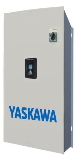
While location is essential to any real estate transaction, you could also apply this requirement to a variable frequency drive (VFD) installation. Selecting the appropriate enclosure for the VFD location will provide the best opportunity for long life.
There are four primary enclosure types for both indoor and outdoor applications. Types 1 and 12 fall into the indoor category. Type 3R and Type 4X are the outdoor category.
When specifying VFDs indoors, consider the surrounding environment.
• Is it clean and conditioned air?
• Is it a dusty manufacturing environment?
• What is the ambient temperature?
• Are there chilled water pipes overhead that are sweating and dripping water?
A clean and conditioned environment would be appropriate for a Type 1 enclosure. A Type 12 enclosure would be appropriate for an indoor area with dripping water or dust — think mechanical room or manufacturing environment with mist spray, dust or other airborne contaminants. The Type 12 enclosure will have filtered ventilation. Types 3R and 4X would be appropriate for an outdoor application where exposure to rain, snow, ice and other precipitation will occur.
Outdoor enclosures will have filtered ventilation and sometimes include a space heater to prevent the formation of condensation. Consider the addition of a space heater in an outdoor application; this small investment upfront that may save the facility manager a big headache down the road. Type 3R is suitable for most outdoor applications.
Type 4X can be designed as a totally enclosed with an air conditioner to remove enclosure heat. Type 4X or stainless steel would be ideal if the enclosure was exposed to corrosive elements. Always consider the cost of Type 4X as it could be multiples higher than a comparable Type 3R.
Most VFDs are rated for sustained maximum output current at 104°F. If the location could exceed this ambient temperature, confirm the manufacturer’s de-rated amperage for higher ambient temperatures. Engineers may have to oversize the VFD for higher ambient temperatures.
Check VFD Supply Voltage, Power Quality & Motor Requirements
Before a building owner installs or powers up a VFD, be sure to check the nameplate data and confirm the voltage to be applied is appropriate. Many VFDs have been damaged on power up because the wrong voltage was applied. Verify all three phases are present or, if single phasing (yes, you can apply single phase power to a standard 6-pulse VFD and generate 3-phase output) that the proper de-rate is applied.
Most populated areas will have clean and true 3-phase power. Outside of major metropolitan areas, power quality may not be as high as expected. Open delta systems are more common in rural areas and may present problems that are beyond the scope of this article. VFD de-rating may be required.
Be sure to confirm motor horsepower (hp) and full-load amps (FLA) and select the appropriate VFD size. The VFD rated output current must meet or exceed the motor FLA. Most motors will have a NFPA 70: National Electrical Code (NEC) amperage to horsepower ratio that will allow for sizing based on horsepower and most fan or pump applications will use a 2- or 4-pole motor, which is more likely to have common NEC horsepower/amperage ratings. Industrial applications that require more torque may use a 6-pole motor and may have higher FLA requirements versus NEC ratings. If this is the case, consider upsizing the VFD to achieve maximum motor speed under full load.
Protection Devices & Understanding SCCR/kAIC
Some VFD manufacturers may indicate a specific short-circuit current rating (SCCR) or kilo ampere interrupting capacity (kAIC), typically between 65 and 100 kAIC. But to attain this specific level, you must specify upstream branch circuit protection. Circuit breakers and/or fuses are installed upstream of the VFD and will interrupt the power in the event of a phase-to-phase or phase-to-ground short circuit. These components and specific SCCR/kAIC requirements exist to lower the risk of an arc flash. Always refer to the manufacturer’s literature to confirm a suitable branch circuit protection for a specific application.
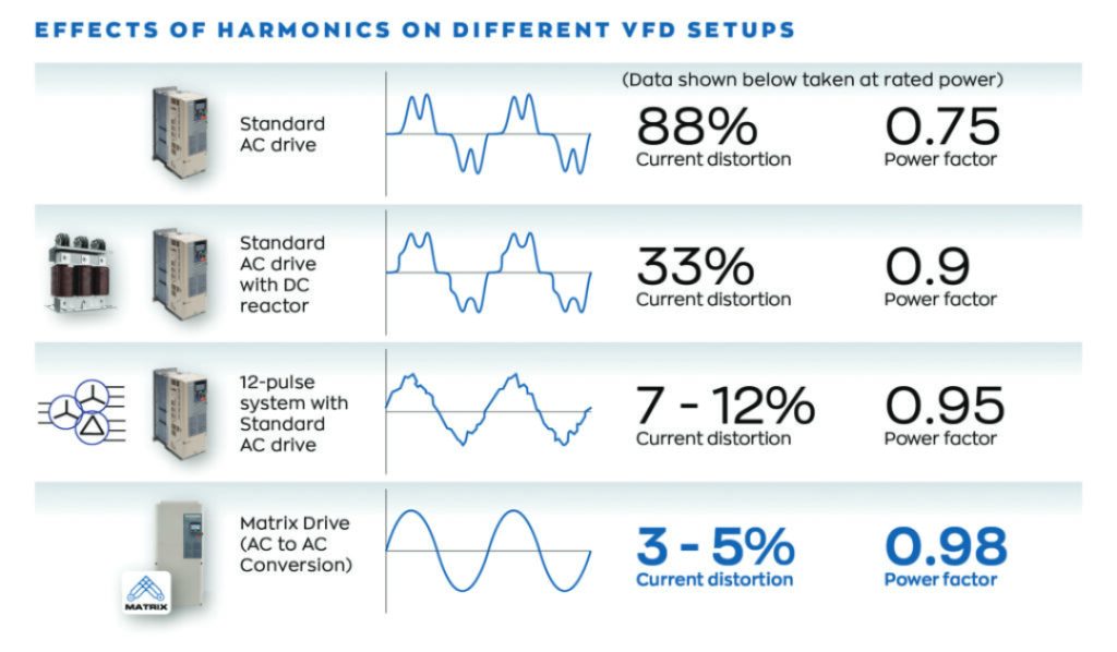
Harmonic Mitigation in VFD Design
The most common type of VFD design is often referred to as a 6-pulse VFD. The 6-pulse VFD has three main parts:
• The input diode bridge, the rectifier where alternating current (AC)-to-direct current (DC) conversion occurs
• The DC bus capacitor bank
• The output transistors or inverter
The power conversion process on a 6-pulse drive may create harmonics (voltage or current distortion) that could adversely affect operation of other equipment on the power system or standby generators.
Devices such as reactors or chokes, which add impedance and smooth out the current draw from the VFD rectifier, will help to reduce harmonics and are sometimes built into the VFD in the DC bus circuit. If harmonics are of concern, such as might be the case in a hospital or airport, proper selection in the preliminary stages of a project is very important. VFDs with direct AC-to-AC conversion and other lower harmonic options are available for these situations.
How a VFD Works & How to Troubleshoot Common Faults
One common fault is an over-voltage. An over-voltage refers to the DC bus voltage exceeding a defined level. The drive disengages motor control and faults out when the DC bus voltage rises too high.
Let’s tie some of the information presented earlier together to help you understand how a 6-pulse VFD works. The input diodes pass the current to keep the DC bus level charged and stable. As the output transistor switches on and off rapidly, creating a simulated ac sinewave, the motor shaft will begin to turn.
A common condition is a regenerative load. Environmental conditions like wind or equipment like additional fans in a plenum may turn the motor shaft faster than the VFD output frequency. If the motor shaft exceeds the rotational magnetic field created by the motor stator the motor has now become a generator. Excess power is now being funneled back to the DC bus through the flyback diodes that are part of the VFD output transistor circuit.
Think of the output side of the VFD as a two-way street. Power goes out but can also come back in. The DC bus has a limited capacity and voltage rise will inevitably trip an over-voltage fault. Once the rotational magnetic field is lost, such as when output frequency ceases upon fault, the motor will freely spin.
Single-phase input is a viable option. Precise motor control is derived from high-speed switching of the transistors on the output side of the VFD that uses DC bus power. This conversion process isolates the AC line side from the output side.
One caveat with single-phase input is that the VFD must be oversized due to the capacity of the DC bus to maintain a stable charge when under load. When one of three phases is eliminated feeding the VFD, the bus voltage will drop too quickly between the next phase. This creates a condition referred to as DC bus ripple, which could damage the capacitors if left unchecked. Most VFDs have a detection circuit to monitor DC bus ripple.
The suggestions only scratch the surface of troubleshooting VFDs. It’s critical to consult the technical information from the VFD manufacturer for specific product questions.